|
Rule 3.9 - Front Body
Mounting Install
Below is my install to meet the new
front body mounting requirements of rule 3.9. In no way is this the only
way to do it but should give you a guide to the process. Once again I
was lucky in that the front body of my car was already off. This made my
install pretty easy and straight forward. Having completed it, I feel
that it could be done with the body on but with considerably more
difficulty in locating the holes.
3.9 Front Body Mounting
To help
prevent intrusion of the body into the driver’s compartment, the cowl
area of the body (the area above and forward of the dash) must be
through bolted to the two ¾” steel tubes on the chassis that extend
forward from the dash hoop into the engine bay. Two 5/16 inch diameter
bolts must be used on each side. Large washers should be used on both
the body and chassis sides to prevent bolt heads from being pulled
through.
Since these
cars are hand made and owner built, the measurements I give below are
only presented to describe the process. Your measurements will more than
likely be different.
I started on the driver side
because of the wind screen. I knew I would have to work around it.
NOTE: You may have to remove and relocate your wind screen. First
you need to figure out where below the body is the ¾” tube. Use whatever
method works for you. The goal at this point was to get a rough idea
where the bolts through the body would hit the ¾” tube. What I found
was that if I put the first hole close to the dash hoop, I could get the
second hole about 1.5” to the front and still clear the windscreen with
room for an oversized washer.
|
 |
 |
|
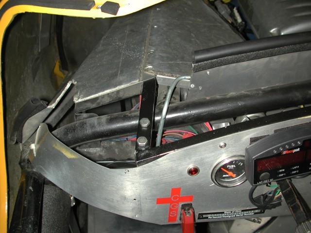
Driver Side-Frame holes
Bolts are inserted just to show hole location. |
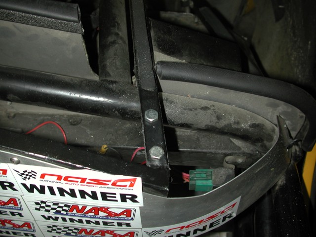
Passenger Side
Bolts are inserted just to show hole location. |
Since there was nothing on the passenger side to work around, I simply
dilled to holes in approximately the same position as the d-side. At
this point, the body was put in place and aligned with the normal body
mounts. Note: Put the bolts in as to assure the body is aligned as it
will be when you bolt everything at the end. With the body in place,
stick your drill bit up through the holes in the ¾” tube from the bottom
and twist it. This will mark your hole on the body. Next the body was
removed and the holes were drilled.
With the holes drilled, put the body back on and check the holes you
just drilled. I did this with a 4” 5/16 bolt. What I found is the holes
in the body were drilled at a slightly different angle. To bring
everything in alignment, run your drill bit down through the body holes
and into the frame holes. This will align the holes.
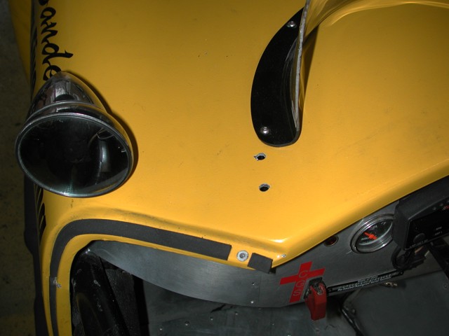 |
 |
| Driver Side |
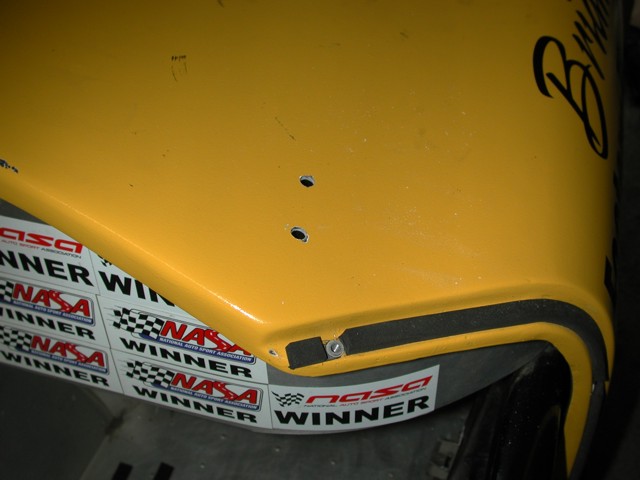
Passenger Side |
By now you may have noticed that you have drilled through a part of the
body that is not horizontal and that the bolt heads will not sit flush
to the body. Also, there is a considerable gap between the underside of
the body and the ¾” tubes. In order for this mounting to be strong and
do what is intended, you will need to fabricate some spacers and decide
what you are going to use on the top of the body.
In my install, I
determined the d-side mounts sat on a 12.5 degree slope and the p-side
was 18 degree. I measured the gap between the body and tubes. Note:
They were different on both sides, 1.125” on d-side and 0.875” p-side.
I cut the above angles into some 9/16” nylon rod that I cut to length
and drilled.
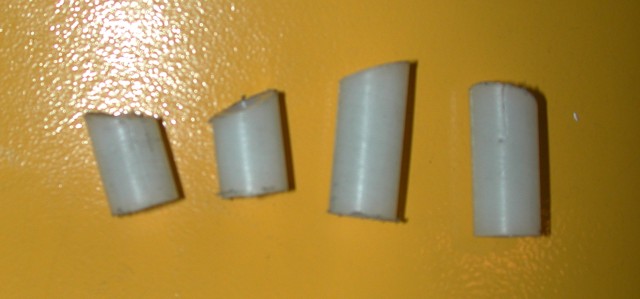 |
| Nylon spacers to go between
body and 3/4" tube. Angle cut to match body. |
As for washers on top of the body,
I looked for a solution but could not find any beveled washers that
would work in this situation. So it was down into the metal shop to
fabricate a solution. Below is my solution. The aluminum pieces are
approximately 1”x2.5”. I milled the body angle into them and they fit
perfect.
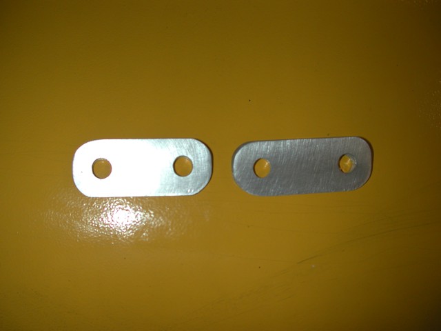 |
|
Fabricated Washers
Cut to
angle of the body. |
 |
 |
| Thin Side |
Thick Side |
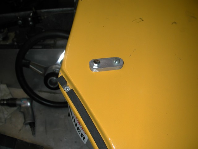
Put it all together and you have a
very strong mount with the load on the bolts distributed properly. You
might get away with using flat washers but my fear was that the body
might tear due to an uneven load under normal conditions.
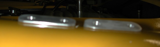
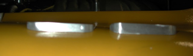
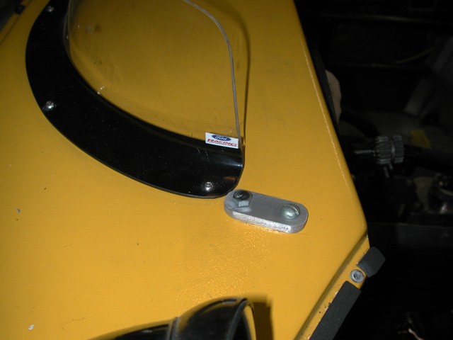 |
 |
|
Driver
side installed
Bolts
only for show. |
Passenger side installed
Bolts
only for show. |
The bolts you see in the above pictures are just
there for demonstration purposes. I plan to use stainless steel button
head cap screws, like the FFR provided body bolts, in the final
installation. For my installation, I ordered 3” bolts for both sides and
Nyloc nuts.
I won’t say this was an easy modification but it is
certainly necessary. Watching a video of my head on collision last year,
I saw just how far the cowl lip of the body intruded into the cockpit. I
was lucky it was on the p-side. Had it been the drivers side, I’m sure
it would have hurt my hands.
--Brian Sanders |